


Product Introduction
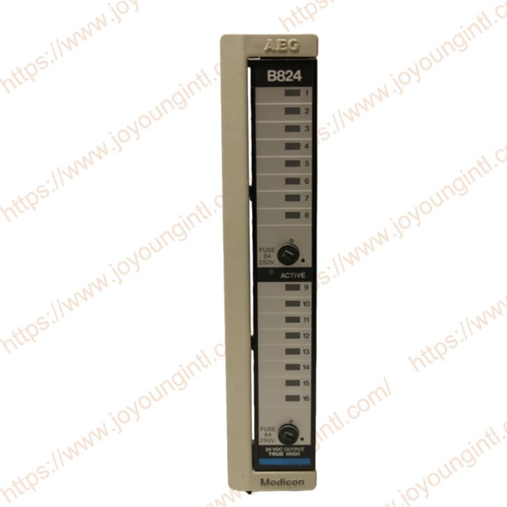
Modicon AS-B824-016 is an Output Module in the Modicon 800 series. The module undertakes the function of the execution layer interface in the system and can perform on-off control of external devices according to the control logic of the PLC program. With 16 independent digital output points, the AS-B824-016 can simultaneously control multiple field loads, making it suitable for automation scenarios that require centralised output control.
Technical Specifications
|
Brand |
Modicon |
|
Model |
AS-B824-016 |
|
Part Number |
AS-B824-016 |
|
Description |
Output Module |
|
Origin |
France / USA |
|
Dimension |
25*20*5cm |
|
Weight |
0.55kg |
Products Description
The AS-B824-016 Output Module in the PLC system acquires the internal working power through the backplane of the rack, which is used to support the logic control, circuit drive, signal isolation and status monitoring functions within the module. The module itself does not generate power. Its internal power supply is completely dependent on the backplane power provided by the PLC host system.
The internal power supply of the module is mainly used to maintain the normal operation of the control logic, photoelectric isolators, output drive circuits and internal monitoring circuits. The internal power supply and the external load power supply are electrically independent of each other, which can effectively avoid the direct impact of on-site load current on the internal electronic circuits of the PLC.
Under normal working conditions, the internal power consumption of AS-B824-016 Output Module remains within a stable range. Internal power consumption does not include any external load current driven by the output point, but only reflects the energy demand of the module's own electronic circuit. Even if the output point is conducting, the current required by the load is provided by an external DC power supply and does not pass through the PLC backplane power supply circuit.
The internal power supply system of the module was designed with the stability of continuous operation in mind, capable of supporting the module to maintain reliable operation under long-term power-on conditions. The internal circuit has a good voltage adaptability and can operate normally within the fluctuation range allowed by the backplane power supply, reducing the risk of false operation caused by power supply changes.
In terms of power consumption management, the module keeps the internal power consumption at a low level through reasonable circuit layout and component selection, thereby reducing the overall heat generation of the PLC rack. This design helps enhance the operational reliability of the system under high-density installation conditions and reduces the requirements for the heat dissipation conditions of the control cabinet.
The power supply and output circuits inside the module are separated through an isolation structure. When a short circuit, overload or abnormal load occurs in the output circuit, external faults will not directly affect the internal power supply system of the module, thereby protecting the normal operation of the PLC main control system and other modules.
During the system configuration and selection stage, users should incorporate the internal power consumption of AS-B824-016 Output Module into the calculation range of the PLC rack power capacity. By rationally planning the number of modules and the backplane power capacity, it can be ensured that the entire control system remains stable and reliable even when operating at full load.
Wiring and Usage Instructions for AS-B824-016
Preparations before Wiring
Before performing any wiring operation, the power supply of the PLC system and the external load must be cut off.
Confirm that the module model used is AS-B824-016 and the output type is 24V DC true high-level output.
Confirm that the rated voltage and current of the external load match the output capacity of the module.
Prepare DC power supplies, wires and terminal blocks that meet industrial control requirements, and ensure that the cross-sectional area of the wires meets the load current requirements.
Explanation of Output Point and Terminal Allocation
The module provides a total of 16 digital output points, numbered from output point 0 to output point 15.
The output points are divided into two groups according to the electrical structure:
Group One: Output points 0 to 7
Group Two: Output points 8 to 15
Each group of output points shares a common terminal for connecting to the external DC power circuit of that group.
The two sets of common terminals are independent of each other and can be connected to different external power circuits.
Description of Typical Wiring Methods
The positive terminal of the external DC power supply is connected to the common terminal of the corresponding output group.
Each output terminal is connected to one end of the corresponding load.
The other end of the load is connected to the negative terminal of the external DC power supply to form a complete circuit.
When the output point is conducting, the module provides a positive voltage to the load, causing the load to act.
When the output point is closed, the output terminal is disconnected, and the load stops working.


If you have any order needs, please feel free to contact us.