


Product Introduction
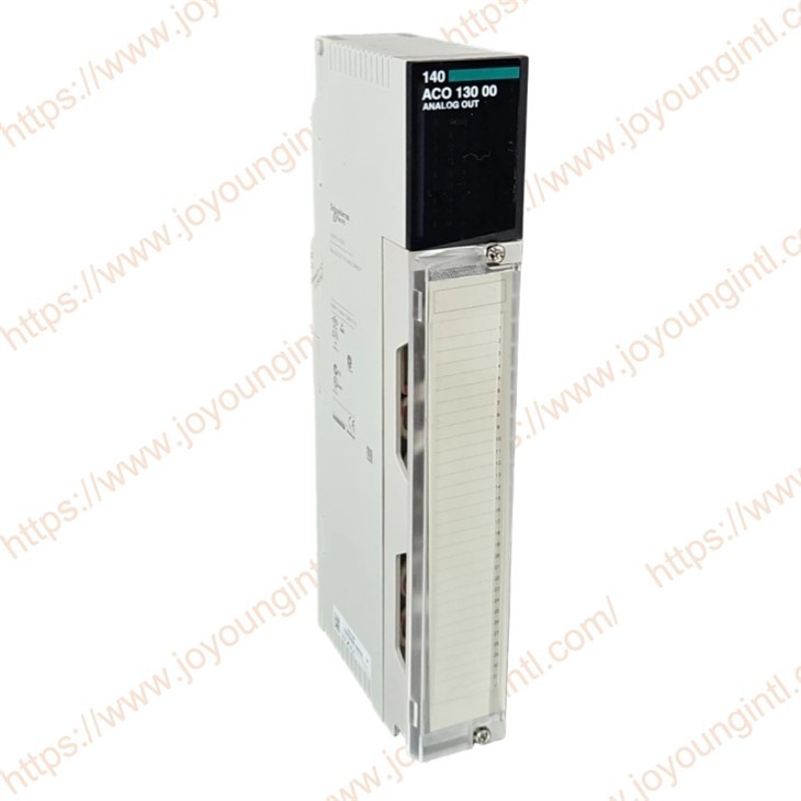
140ACO13000 analogue output module is designed for use with the Modicon Quantum automation platform. It provides multiple output channels for field signal transmission to actuators or external devices. The module supports a range of current output formats and includes local indicators for channel status and fault conditions.
Technical Specifications
|
Brand |
Schneider |
|
Model |
140ACO13000 |
|
Part Number |
140ACO13000 |
|
Description |
Analog Output Module |
|
Origin |
France |
|
Dimension |
18*13*5cm |
|
Weight |
0.3kg |
Product Details
The 140ACO13000 analog output module is an 8-channel analog output device designed for the Modicon Quantum automation control system. It can convert PLC control logic into standard current output (such as 4...) 20 mA / 0… 20 mA / 0… 25 mA), for on-site equipment such as control valves, frequency converter modules, transmitters, etc. The module supports multiple typical analog output ranges and provides channel electrical isolation and on-site LED indication, facilitating real-time on-site viewing of output status and fault information. The response update time of the module is approximately 5 ms, adapting to the output requirements of various industrial control scenarios.
Wiring diagram description - 140ACO13000 Analog Output Module
 Module terminals and identification instructions"RETURN terminal"
1. All terminals marked "RETURN" have a Common connection point inside. When wiring, these RETURN terminals are typically used as the common negative terminals of the analog output circuit or as reference points for the circuit.
2 . Output channel terminal (AO1...) "AO8
The module provides 8 analog output channels, corresponding to 8 independent output signals.
Each analog output channel is generally composed of a signal output terminal and the corresponding RETURN terminal, which is used to connect with field devices such as valve controllers, frequency converters, actuators, etc.
3.Power supply and circuit power supply
External loop power support 6... 30 V DC. It is recommended to select the appropriate power supply according to the specifications of the connected load.
The output signal will eventually be affected by the voltage of the power supply circuit. Avoid excessive voltage drop that may affect the output accuracy.
Precautions and wiring instructions
Multi-channel shared RETURN
All terminals marked as "RETURN" are shared within the module.
When multiple channel outputs need to be grounded in a loop or connected to the same reference point (such as the negative terminal of a power supply or a common circuit), they can be connected to the same RETURN terminal.
External power supply and module power supply
The external power supply device must meet 6... The power supply requirements for the 30 V DC loop ensure the stability of the power supply for the analog signal loop.
If the load equipment requires an additional power supply, it is necessary to ensure a consistent voltage reference for the two systems during on-site wiring.
Avoid voltage drop exceeding the allowable range.
Due to the voltage limit of the output circuit (<30 V at 25 mA), it is recommended to use an appropriate power supply and wire gauge to avoid excessive voltage drop caused by long wire distances.
Local indicator lights and diagnostic wiring assistance
Although it is not a direct wiring content, local LED indicators are helpful in actual wiring and debugging:
The green LED indicates that the module communication exists or the channel is activated.
The red LED indicates faults in the external circuit or incorrect channel indications.
These status indicators can assist with on-site wiring debugging and fault diagnosis.s
If you have any order needs, please feel free to contact us.