


Product Introduction
Woodward 1751-6091 Discrete Output Relay achieves the bridging of on/off signals between the control system and external electrical loads through internal relays. It can achieve electrical isolation and drive conversion between the logic output of the control system and the load of the on-site equipment.
Technical Specifications
|
Brand |
WOODWARD |
|
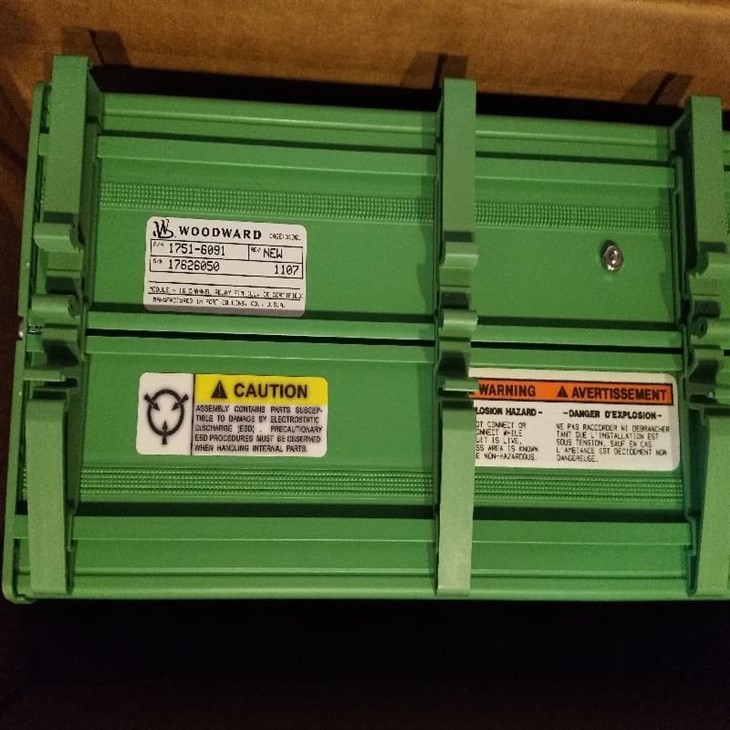
Model |
1751-6091 |
|
Description |
Discrete Output Relay |
|
Origin |
USA |
|
Dimension |
45*20*15m |
|
Weight |
1.35kg |
Product Details
1751-6091 is mainly used as a relay output module, and its functions include:
This module is equipped with 16 independent relay channels, and each channel can control the on/off status of an electrical device.
2. Relay Capacity
Each channel's relay can handle certain currents and voltages for on/off loads (the specific values need to be checked in the official instructions or on the equipment label). As a switching device, relays inherently possess an electrical isolation function, which helps to ensure a safe isolation between the control signals and the high-voltage or high-current equipment in the field.
1751-6091 usually receives control signals from the upper-level controller (such as PLC, DCS, speed governor, or logic control unit):
The control logic signals can come from a digital output (DO) or a relay driver.
The module converts these control signals into actions to drive relays.
The module will output the logical signal through relays to drive the equipment at the site: Motor.
Electromagnetic valve
Indicator lights
Heater
Other loads that require on/off control
This architecture ensures electrical isolation between the control system and the on-site execution circuits, as well as load amplification functions, which are of vital importance for the security of industrial control systems.
Work scenarios and typical applications

The main function of 1751-6091 is to convert the output logic of the control system into on/off control for physical electrical devices.
In large-scale industrial automation systems, such as:
DCS or PLC systems in power plants
Control cabinets for construction machinery
Petrochemical production lines
Metallurgical equipment, Water treatment automation facilities
The control system will issue multiple logical output instructions, such as:
"Start pump.p A"
"Close Valve B"
"Start the cooling. fan"
"Triggering the alarm signal" etc.
These instructions need to be driven by the relay module to operate the actual load circuit. The 16-channel relay output of 1751-6091 precisely meets the requirements of complex control logic.
2. Generator and Speed Control Auxiliary Module
1751-6091 is often used in conjunction with the following systems:
Digital Governor
Generator Set Control Box Speed/load monitoring system
3. Installation Method
1751-6091 supports DIN rail mounting (DIN Rail mount), which means it is installed on the internal rails of the control cabinet.
Control module compliant with industrial electrical standards
The output terminals are arranged neatly in multiple channels, facilitating on-site cable connection
FAQ

0 1. What should be noted before installing 1751-6091?
The circuits within the control cabinet may contain high voltages (such as 24 V control, 110 V or higher), and improper operation can easily lead to electric shock accidents.
02 . Ensure that the control logic matches the output function.
✔ Ensure that the output logic (such as who to connect and who to disconnect) is consistent with the actual on-site operation requirements;
✔ Use the correct triggering conditions to avoid incorrect actions or electrical conflicts.