Item Number:IS215VAMBH1A
Brand: GE
Price: $11000
Lead Time: In stock
Condition: New
Payment: T/T
Shipping Port: Fujian
Send Inquiry
Description
Technical Parameters
Product Introduction
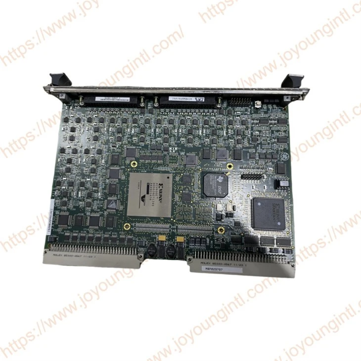
The Acoustic Monitoring (VAMB) board provides 18 channels of signal conditioning through two nine channel acoustic monitoring terminal boards IS200TAMB (TAMB) and one 18 channel I/O acoustic monitoring sub-assembly IS215VAMB (VAMB). The TAMB supports third party vendors such as, Bentley-Nevada*, Vibro-Meter®, GE/Reuter-Stokes*,and others.
Technical Specifications
Manufacture
General Electric(GE)
Model
IS215VAMBH1A
Part Number
IS200VSPAH1ACC
Description
Mark VI Controller
Origin
USA
Dimension
30*20*6cm
Weight
0.35kg
Product Details
IS215VAMBH1ACompatibility:
The selected product combination determines the system requirements as follows:
• 18 channels of signal conditioning for sensing dynamic pressure output from third party charge amplifiers
−Bentley-Nevada, Vibro-Meter, PCB Piezotronics®, GE PS CCSA and GE/Reuter-Stokes vendors are supported
−Differential inputs and adjustable gains
−Fast synchronous-sampled analog/digital with 8x over-sampling capability to minimize analog filtering
−Alarm detection if peak amplitude exceeds configurable level
−List captures capability for all 18-channels if an alarm is detected
Installation:
The following figure displays the functionality of one of the nine channels supported on the TAMB. Each channel provides current limited +24 V dc and +24 V dc power supply outputs. A constant current source is connected to the SIGx line for the PCB sensors. The input signal, CCSELx, is False when the signal is a logic-level low through an output on the VAMB. At power-up, the output must be False (logic-level low), leaving the constant current output deselected until the configuration parameters are loaded.
Open Connection Detection:
A high impedance dc bias allows the VAMB to detect an open connection between the charge amplifier or sensor and the TAMB. The dc bias control provides three options:
• 28 V bias or ground applied to the signal line
• SIGx and return line
• RETx
FAQ: Fault Description & Possible Cause
Q: Fault 2:Flash Memory CRC Failure
A: Board firmware programming error (board will not go online)
Q: Fault 16:System Limit Checking is Disabled
A: System limit checking was disabled by configuration
Q: Fault 18:Incorrect J3 Terminal Board ID
A: Cable to J3 connector not properly connected to a TAMB terminal board or terminal board defective.
A: A tre file has been installed that is incompatible with the firmware on the I/O board. Either the tre file or firmware must change. Contact the factory.
Q:Fault 38:Flashdisk error: Unable to revert to flash configuration after remote access
A: Permanent configuration data on card is corrupted. Download firmware to card or replace card.
Q: Fault 41-58:Sig x: Open Ckt Test Failed. Check Wires and Sensor
A: Open circuit detected for terminal board signal Sigx, where x is the identified point. Check wiring and sensor.