


Product Introduction
GJR23922700R1210 83SR07F-E has no hard-wired control room interfaces; activation is effected over the bus.A higher-level automatic system controls the module over the bus.The logic links for protection commands are defined depending on the plant specifics.In the case of drive control functions, the actuator-related checkback signals from the process can be connected via the hardware inputs of the module. The two analog inputs of a process interface are intended for internal purposes only and must be connected to the respective inputs of the drive control function ASP.

Technical Specifications
|
Manufacture |
ABB |
|
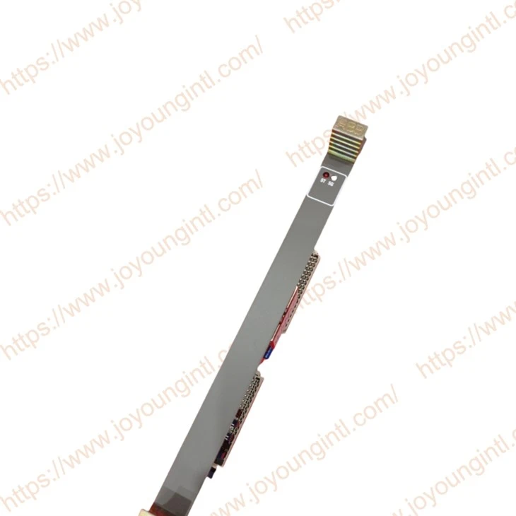
Model |
83SR07F-E |
| Part Number | GJR23922700R1210 |
|
Description |
Procontrol Control Module |
|
Origin |
Germany/SWITZERLAND |
|
Dimension |
30*21*5cm |
|
Weight |
0.5kg |
Product Details
For structuring, the neutral inputs and outputs of the individual function blocks are assigned certain module inputs and outputs, or the inputs of the function blocks are assigned fixed values and parameters or outputs of other function blocks (function results). Structuring is performed on the basis of data supplied by the user in the form of a so-called structure list. For structuring, the following limit values of the module need to be taken into consideration:
- Max. number of module inputs 287
- Max. number of simulatable function results, module inputs and outputs 32
- Max. number of module outputs 223
- Max. number of function results 255
- Max. number of timers 136
- Max. number of parameters 80
- Max. number of limit value sets 16
- Max. number of ASP drive control functions 2
- Max. number of lines in the structure list 2823
- Length of history value list (bytes) 1024
- Size of shared memory (cf. "Addressing")
A line is understood as one entry on the PDDS. For the precise procedure of structuring the function blocks, please refer to the respective function block descriptions.
Signal exchange between the module and the bus system takes place via a shared memory. In this shared memory, incoming telegrams which the module is to receive and function results which are to leave the module, are buffered. For this purpose, the shared memory includes send registers for telegrams to be sent and receive registers for telegrams to be received. Register numbers 0 through 63 are defined as send registers, and register numbers 64 through 199 are defined as receive registers. The allocations of the module input and output signals to the registers of the shared memory are defined as specified by the user via the PDDS.
The telegrams received over the bus may have a fault flag set in bit position 0. The fault flag is generated by the sending module based on plausibility checks and is set to "1" if specific disturbances occur (cf. the relevant module or function block descriptions). In order to be able to recognize errors in signal transfer, the module includes a feature that monitors the input telegrams for cyclic renewal. If a signal has not been updated for a particular period of time (e.g. on account of a failure of the sending module), the bit of position 0 in the assigned receive register of the shared memory will be set to "1". At the same time, all binary values are set to "0" in binary value telegrams. In the case of analog values, the previous value is retained. A set disturbance bit does not automatically trigger a reaction in the module. If the disturbance bit of a telegram is to be evaluated, this must be taken into consideration when structuring. The disturbance bits of received telegrams can only be used internally. They are not included in telegrams to be sent.
