













Product Introduction

Technical Specifications
|
Manufacture |
ABB |
|
Model |
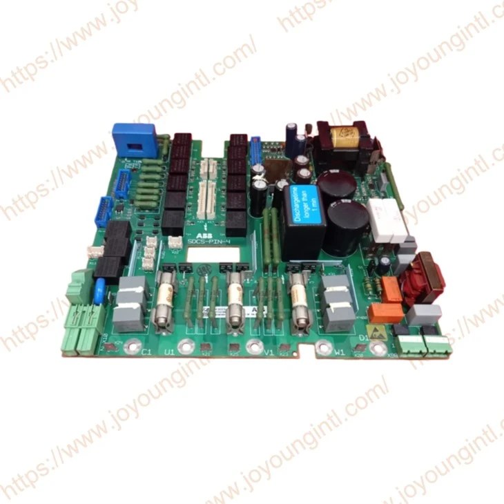
SDCS-PIN-4 |
| Part Number | 3ADT314100R1001 |
|
Description |
Interface Board |
|
Origin |
Finland |
|
Dimension |
25*25*5cm |
|
Weight |
0.5kg |
Product Details
The SDCS PIN4 board is designed for DCS800 Converter modules sizes D1 up to size D4 (20 A...1000 A). The board has three different functions:
1. Power supply of the CON-4 board and the connected options
2. Control of armature bridge and measurement
3. Control of on-board field exciter and field current measurement
The board is mounted with conducting ground at points inside the module.
The board is used for supply voltages from 230 V up to 525 V, 600 V.
The converter identification is made by TYPECODE 97.01 (and not by hardware)!
The converter identification manages the burden resistor setting and 2-Q or 4-Q bridges operation.
 Power supply:
The power supply (X99:) operates on fly flyback configuration. The internal DC link voltage is 310 V.
The power supply automatically adapts the supply input voltage between 230 V and 115 V and switches relays K301.
In case of oscillating 230 V input voltage (e.g., generator network), the operation must be clamped to 230 V by JumpeS11 2-3 230 V operation.
Armature circuit interface:
The function for the armature circuit interface consists of:
• Firing the armature bridge of 6 or 12 thyristors.
• High ohmic measurement of DC and AC voltage.
• Interface for an AC transformer for current measurement.
• Snubber circuit for the thyristor protection together with resistor R1 on the heatsink.
• Interface for heatsink temperature measurement with a PTC resistor.
• Fuses for overvoltage protection and the field circuit.
The same board can be used for 3-phase field exciters without modification.
The current measurement is adjusted by the TYPECODE parameter 97.01 and automatically adjusted by the rated motor current.
Field circuit interface:
The onboard field exciter is located internally. The firing pulses are synchronized from the mains circuit L1, L2,, L3 the nd SDCS-CON-4 board. The pulses are amplified on the PIN4 board. The hardware structure is a three-phase half-controlled bridge supplied directly from the mains circuit U1, V1, W1 via fuses F100, F101, F102.
If the Ooard field exciter is not needed, it can be switched OFF by the firmware.
The function of the field circuit interface consists of:
• Firing the field bridge, three three-phase half-controlled bridge.
• Measurement of DC field current, the scaling is automatically selected via the rated motor field current.
• Snubber circuits are shared with the armature bridge.
• Fuses F101, F102, F103 for cable and motor field protection.