


Product Introduction
ABB 07KT92 GJR5250500R0202 is designed specifically for ABB control systems. This module is ideal for compact applications requiring simultaneous status monitoring (e.g., pushbuttons, switches, sensor signals) and actuation control (e.g., indicator lights, miniature relays, solenoid valves). By integrating input and output functions into a single module, it significantly saves control cabinet space and hardware costs, making it ideal for small control systems or distributed I/O stations.

Technical Specifications
|
Manufacture |
ABB |
|
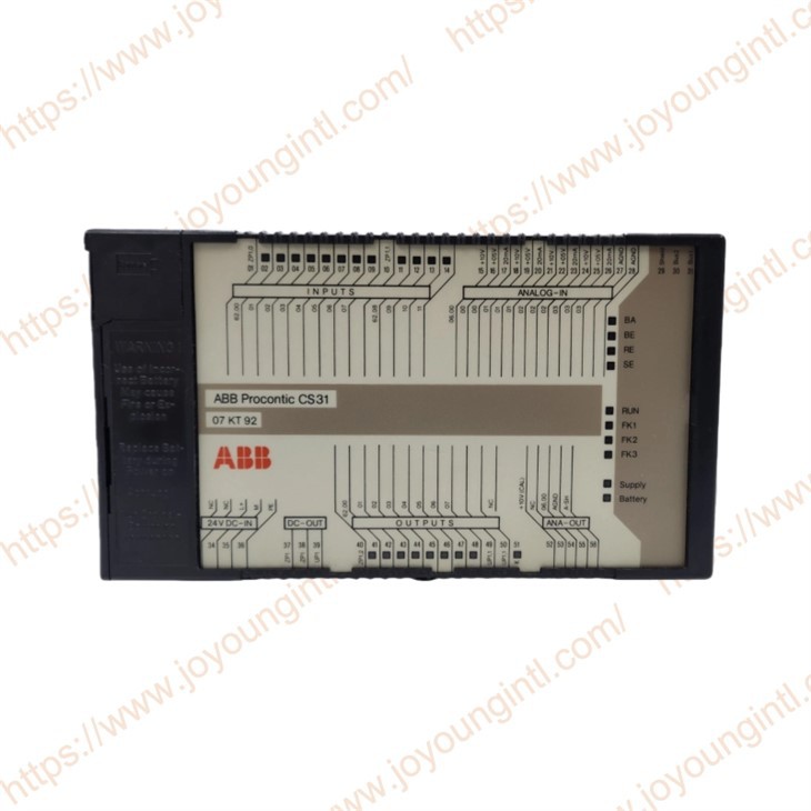
Model |
07KT92 |
| Part Number | GJR5250500R0202 |
|
Description |
Basic units |
|
Origin |
Germany |
|
Dimension |
15*15*12cm |
|
Weight |
0.81kg |
Product Details
Access to the AC31/CS31 basic units (07 KR 31, 07 KR 91, 07 KT 92 to 07 KT 94) and to the communication processor 07 KP 62 of ABB Procontic T200 is conducted via the serial interface COM1.
Connectable units:
– Terminal in the VT100 mode
– Computer with VT100 emulation
– Computer with a program for the handling of the clear text telegrams of the operating and test functions
The serial interface COM 1 must be set to the operating mode "Active mode" to use the operating and test functions.
RUN/STOP switch in position: STOP. In the switch position ST, O, P, the PLC generally sets the operating mode "active mode" on COM 1.
RUN/STOP switch position.RUN In the switch position, RUN the operating mode "active mode" is set on COM 1, when one of the following two conditions is fulfilled:
– System constant KW 00,06 = 1
or
– System constant KW 00,0,6 = 0 and Pin 6 on COMa 1 has 1-signal (1-signal on Pin 6 is set by using the system cable 07 SK 90 or by not connecting Pin 6)
The following applies:
The processing of the PLC program has higher priority than the communication via the serial interfaces.
The PLC operates the receiving direction of the serial interface COM1 with interrupt control. During a running PLC program cycle, incoming characters respectively trigger an interrupt impulse, which interrupts the running PLC program until the received characters are stored in the reception buffer. To avoid a permanent interruption of the program processing, the PLC controls the data reception via the RTS line so that it takes place in the breaks between two PLC cycles.
The PLC processes the jobs received via COM1 exclusively in the breaks between the PLC program cycles. The output of characters via COM1 is also only conducted in the breaks between two program cycles. The lower the utilisation rate of the PLC is, the longer the breaks are between the program cycles and the higher the possible communication rate is to COM1.
Synchronisation of the data exchange:
The synchronisation of the data exchange between the control and the connected unit is conducted via the hardware handshake lines RTS and CTS.
The PLC blocks data reception via the RTS line under the following limiting conditions:
– Reception buffer has reached a certain fill.
– A PLC program cycle is just running.
The control still reacts during output of characters in addition to the XOFF/XON characters of the connected unit. The control itself does not use these SW handshakes.
In the breaks between two PLC program cycles, the PLC processes the jobs collected in the reception buffer. To do this, the characters are read out of the interrupt-controlled reception buffer by the PLC, immediately echoed via COM 1, checked for correct syntax, and then processed. The characters are echoed in the same order as received via COM 1.
Popular models:
| 07DO90-S | 07KT95 |
| 07KP90 | 07KT97F1 |
| 07DC91 | 07KT97C |
| 07DC91 | 07KT97D |
| 07MK92 | 07KT97B |
| 07KT94 | 07KT97C |
| 07KT94D | 07KT97 |
| 07KT94K | 07KT97B |
| 07KT94i | 07KT97B |
| 07KT94 | 07KT97B |
| 07DC92 | 07KT97B |
| 07DC92E | 07KT98E2 |
| 07DC92F | 07MK92 |
| 07DC92B | 07DI92 |
| 07AC91 | 07KT95 |
| 07KR31 | 07MK62 |