


Product Introduction
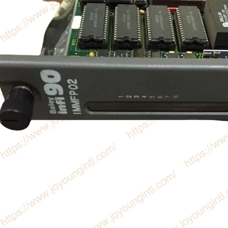
The IMMFP02 Multi-Function Processor Module (MFP) is one of the workhorses of the INFI 90® control module line. It is a multiple loop analog, sequential, batch and advanced controller that provides powerful solutions to process control problems. It also handles data acquisition and information processing requirements providing true peer-to-peer communications. The comprehensive set of function codes supported by this module
handles even the most complex control strategies. The INFI 90 system uses a variety of analog and digital I/O modules to communicate with and control the process. The MFP module communicates with a maximum of 64 modules in any combination.

Technical Specifications
|
Brand |
ABB Bailey |
|
Model |
IMMFP02 |
|
Part Number |
IMMFP02 |
|
Description |
Multi-Function Processor Module |
|
Origin |
USA |
|
Dimension |
36*28*8cm |
|
Weight |
1.2kg |
Product Details
The MFP module has three operating modes: execute, configure and error. In the execute mode, the MFP module executes control algorithms while constantly checking itself for errors. When an error is found, the front panel LEDs display an error code corresponding to the type of error found. In the configure mode, it is possible to edit existing or add new control algorithms. In this mode, the MFP module does not execute control algorithms. If the MFP module finds an error while in execute mode, it automatically goes into error mode. Refer to the Section 4 of this instruction for operating mode details.
A one megabaud CPU to CPU communication link allows the MFP module to accommodate redundant processors. This link enables a backup MFP module to wait in a hot standby mode while the primary MFP module executes the control algorithms. If the primary MFP module goes off-line for any reason, a bumpless transfer of control to the backup MFP module occurs.
SETUP AND PHYSICAL INSTALLATION
This section explains how to configure and install the MFP module. After installing the MFP module, a function block configuration must be created to define the functions the module will perform. This configuration can be created in the module itself or can be created using a configuration tool (e.g., CAD/ TXT, EWS) and then downloaded to the module.
The MFP module has two configurable dipswitches and five jumpers. Each dipswitch has eight poles. See Figure 3-1 for dipswitch and jumper locations. Dipswitch SW3 sets the bus mode and module address. Dipswitch SW4 sets module options and special operations (refer to Special Operations of this section). Jumpers J1 through J5 are for special applications.
Dipswitch poles marked unused in tables must be kept in the zero position. The MFP module may not operate properly if these dipswitches are set to the one position. Since factory settings do not reflect default settings, it is imperative that all dipswitch settings be checked before putting the module into operation.

FAQ
Q: How is the packaging of the products?
A: The products will be packaged in standard and safe cartons for shipping. If you require additional wooden case reinforcement, please let us know in advance before shipment. Note that this service will incur an extra cost.
Q: What are your warranty terms?
A: We provide varying warranty periods for different products. By default, new original products come with a one-year warranty. If you have specific requirements regarding the warranty period, please contact us for detailed terms.
Q: Are your products brand new and original?
A: Yes, our products are brand new and original, and they come with a one-year warranty.